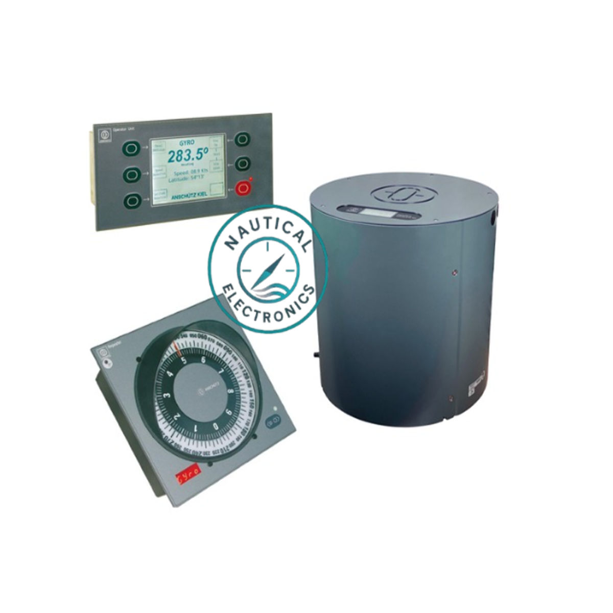
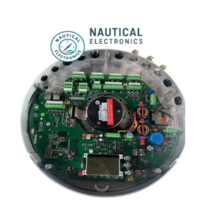
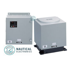
Raytheon Anschütz Kiel Standard 22 Gyrocompass
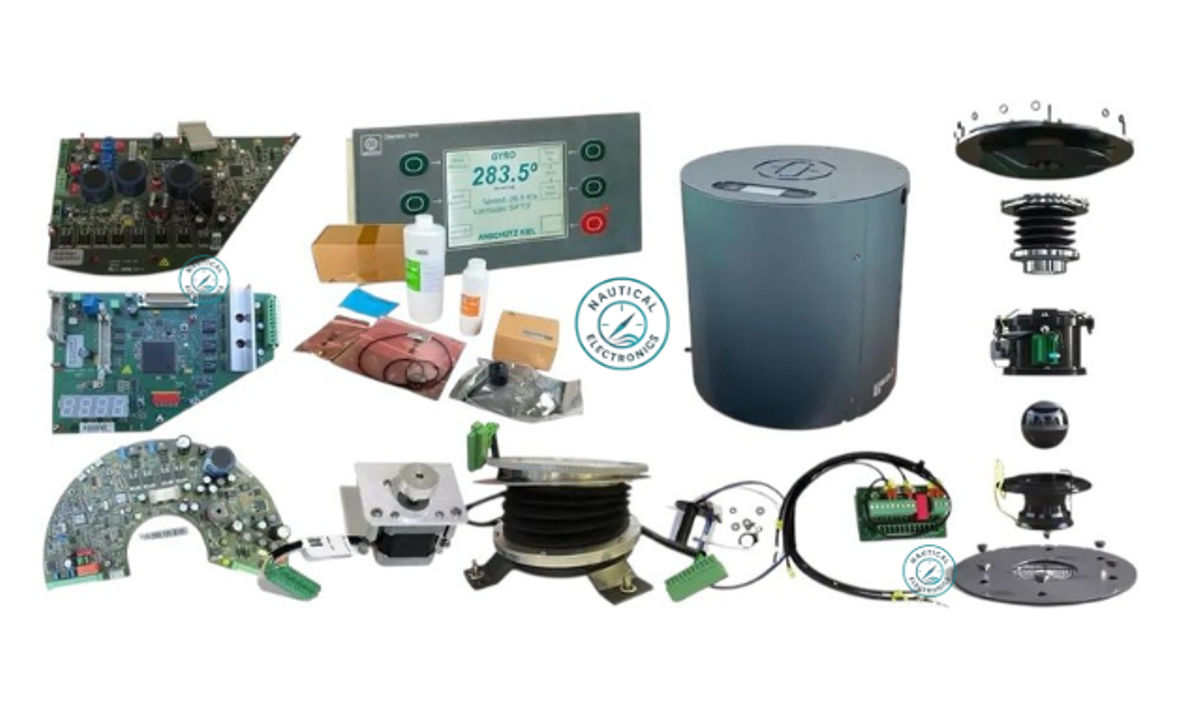
The Standard 22 Gyrocompass from Raytheon Anschütz Kiel is a trusted solution providing all essential spare parts and detailed support for smooth operation. The system includes the Std22 Gyrosphere, multiple printed circuit boards (PCBs), a comprehensive Service Pack, and a range of optional components tailored to your needs.
Renowned for its reliability and precision, the Standard 22 Gyrocompass ensures accurate heading data for safe and efficient maritime navigation. Choose the Standard 22 for robust performance and uninterrupted service on every voyage.
Standard 22 Gyrocompass Components
Below is an overview of the core and optional parts available. Please refer to the specific part numbers (PN) when placing inquiries, as each component is uniquely identified to ensure proper functionality and compatibility.
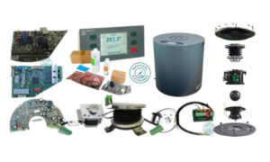
Gyro Compass Main Unit – Part Number: 110-233
The core component of the Standard 22 Gyro Compass system, delivering precise orientation and reliable navigation performance. Designed for seamless integration, it enhances the overall system accuracy and durability.
Included Components:
-
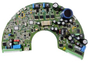
Power Supply PCB – 110-233.X12
-
Outer Sphere PCB – 110-233.X10
-
Connection PCB – 110-233.X13
-
Sensor PCB – 110-233.X11
-
Encoder – 110-233.X01
-
Hinge Unit – 110-233.11
-
Cable Loom – 110-233.28
-
Terminal PCB with Temperature Sensor – 110-233.X09
-
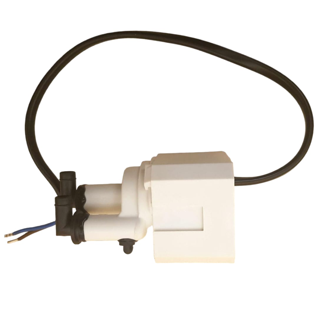
Pump Unit – 110-231.40
-
Heater Unit – 110-231.X01
-
Outer Sphere Complete – 110-233.X04
-
Supporting Liquid – 148-162 E01
-
Distilled Water – 148-398
-
Filler Pipe – 148-398.00-002
-
Set of Gaskets – 110-222.X01
-
Set of Small Parts – 110-233.X50
-
Fan – 110-233.00-002
-
Step Motor – 110-233.47
Detailed descriptions of each part number are provided below.
Power Supply PCB – 110-233.X12
Power Supply PCB – Function and Error Codes
The Power Supply PCB generates all necessary voltages required for the gyrocompass to operate correctly. It continuously monitors system performance and reports malfunctions via specific error codes displayed on the unit’s screen.
Error Codes and Meanings:
-
EL 01: Faulty serial connection between Sensor PCB and Power Supply PCB
-
EL 02: Inductive transmission failure
-
EL 03: Abnormal system voltage detected on Power Supply PCB
-
EL 04: Encoder voltage malfunction
-
EL 05: System voltage fault on Power Supply PCB
Outer Sphere PCB – 110-233.X10
Sensor PCB – Function and Error Codes
The Sensor PCB ensures accurate voltage transmission to the Gyrosphere, which is essential for obtaining precise heading information. It also monitors system status and reports any issues through specific error codes.
Error Codes and Descriptions:
-
EL 10: Supporting liquid error
-
EL 11: Faulty system voltage on sensor PCB (B21.5 ⇒ B21.8)
-
EL 12: Operating voltage 24V malfunction
-
EL 13: Operating voltage 15V malfunction
-
EL 14: Heating operating voltage (B21.1 ⇒ B21.4) faulty
-
EL 15: Operating voltage 72V malfunction
-
EL 16: Operating voltage 78V faulty for 400 Hz
-
EL 17: Gyro supply 55Veff malfunction
-
EL 18: Gyro current faulty
-
EL 19: Pump voltage malfunction
-
EL 20: Pump current malfunction
-
EL 21: Temperature sensor failure
-
EL 22: Faulty serial interface between MC1 and MC2
-
EL 23: CAN interface fault from outer sphere PCB to sensor PCB
-
EL 24: Heating system malfunction
Connection PCB – 110-233.X13
Connection PCB – Function and Error Code
The Connection PCB manages the distribution of the main supply voltage and communication lines throughout the gyrocompass. It facilitates reliable communication between all connected components.
Error Code:
-
EL 09: Fault detected in CAN1 and CAN2 operating voltage
Sensor PCB – 110-233.X11
Encoder Unit – Functions and Error Codes
This unit oversees all device versions, software processes, and critical mathematical operations. It integrates key components necessary for observation and system diagnostics.
Error Codes:
-
EL 06: Encoder malfunction
-
EL 07: Fault in CAN communication from outer sphere PCB to sensor PCB
-
EL 08: Follow-up system error
Encoder – 110-233.X01
Sensor PCB – Role and Error Codes
This PCB processes data from the Gyrosphere to provide accurate ship heading information. It continuously monitors system functionality and reports errors via specific codes.
Error Codes:
-
EL 04: Encoder voltage fault
-
EL 06: Encoder malfunction
Hinge Unit – 110-233.11
Hinge Unit
Provides structural support to the Gyrocompass container and Gyrosphere, maintaining stability even during ship motions.
Cable Loom – 110-233.28

Cable Loom
Links the Outer Sphere PCB to the Terminal PCB, enabling effective communication between these units.
Terminal PCB with Temperature Sensor – 110-233.X09
Terminal PCB with Temperature Sensor
Connected to the Outer Sphere PCB through the Cable Loom, this unit monitors and regulates the Gyrosphere’s operating temperature.
Pump Unit – 110-231.40
Pump Unit
Responsible for circulating fluid inside the Gyrosphere. It monitors voltage and current levels to ensure proper operation. Regular replacement is recommended to maintain optimal performance.
Error Codes:
-
EL 19: Pump voltage fault
-
EL 20: Pump current fault
